What is antenna radome?
Radomes are large, dome-shaped structures that protect radar systems from bad weather conditions. The radomes allow electromagnetic signals to be received by the radar without distortion or attenuation.
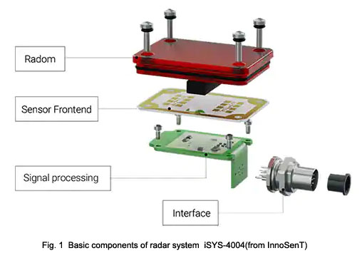
Radar sensor is composed of a front end (RFE) (microwave component with antenna structure) and components for signal processing. The front end is the actual core of radar because it is the part where the antenna transmits and receives electromagnetic signals. In order to interpret the collected information, the front end forwards it to the signal processing unit (Fig. 1).

In order to protect the radar antenna and electronic components, the sensor is usually enclosed in the shell. This protects the RFE from damage or performance degradation caused by external influences. Because of its ability to penetrate materials, radar is often favored because of its beautiful appearance. This aspect is especially appreciated by product designers.
When it comes to the protective shell of the antenna structure, radar technicians refer to the “radome”.
The word is a combination of “radar” and “dome”. As on the iSYS-6003, the dome is mainly used for fixed installation of large radar systems, such as aircraft or ship radar.
However, sensors and systems used in industrial or commercial applications also need to prevent mechanical or chemical effects so as not to damage the function of the antenna. These are for the purpose of applying to the antenna and conforming to the characteristics of radar waves.
Material of the antenna radome:
In addition, it is also important to use the correct materials when designing the radome. If an object or human body is encountered in the process of electromagnetic wave propagation, the characteristics of the material will affect the propagation. In order to find suitable materials for radomes, it is important to consider their impact after encountering radar waves.
Table 1 summarizes the microwave absorption and reflection characteristics of various materials and the penetration of microwaves to these materials.
| Material | absorption | reflection | penetration of microwave |
| Metal | Nil | Vertical incidence, complete reflection, oblique incidence, refraction and partial reflection may occur | Almost impossible (only penetrate into the surface and nano thick bottom) |
| Wood (depending on humidity) | Medium to high | Low | Low |
| Water | Very high | Depending on the incident angle, partial or complete reflection may occur | Nil(Reasons for absorption) |
| Foam (e.g. polystyrene, insulation) | Low | Nil | Excellent |
| Plastic | Low to high (depending on the thickness of the material) | Low to high (depending on material, thickness, distance) | Low to high (depending on material, thickness, distance) |
Radar waves must be able to penetrate the radome. Metal will shield the radar sensor. Due to its high reflection characteristics, metal is not suitable for placing in front of the antenna. Wood paneling (usually with a certain residual humidity) is also not suitable because the penetration of electromagnetic waves is limited.
Polystyrene and other foam are very suitable for covering materials, and can even be directly wrapped on the antenna without processing. However, because of the low stability and sensitivity to chemicals, foam is often lost when selecting materials.
Therefore, plastic is the most common alternative material for the production of protective covers or shells. However, when designing radomes, designers must consider the characteristics of plastics. The thicker and closer the material is to the antenna, the less electromagnetic waves penetrate.
In the case of black plastic, there may be lost during measurement, because this kind of plastic usually contains carbon. In addition, the stagnant water that cannot be drained will also have an adverse impact on the front-end information collection. The subsequent treatment of plastic radomes, such as painting, will also have a negative impact on the data acquisition of radar antennas.
Size and location of Radome
When constructing a radome, it is not only the material selection of the radome but also the accurate fixation and shape. In order not to limit its function, the following aspects must be considered:
- Distance between radome bottom and antenna
- The thickness of radome material
- Radome shape (as uniform as possible)
These factors determine whether most radar waves will be reflected or absorbed by the constructed radome.
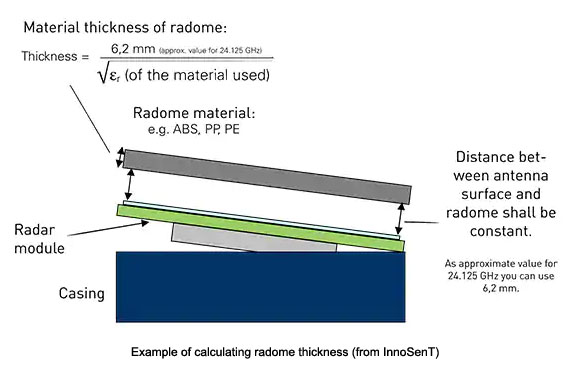
The uniformity of distance from radome to antenna is very important. Even minor deviations, such as a small notch at the bottom of the protective cover, will change the propagation of electromagnetic waves. For this reason, tilted radomes can also have an adverse effect, as they may affect normal reflection.
In order to determine the correct and uniform distance, the following conditions apply:
If the distance to the radome is exactly half (or multiple) of the wavelength, the propagation of the wave will only be slightly disturbed.
This means that the antenna surface (wave center) must be placed parallel to the radome at a distance of λ/ 2 (or multiple thereof).
When the center frequency is 24.125 GHz (half of the wavelength is about 6.2 mm), the optimal distance is about 6.2 mm.
Proper material thickness of radome
In this regard, the same principle for determining the appropriate distance can be adopted: in order to minimize the interference of wave propagation, the radome should be placed at half the wavelength. Similarly, the appropriate radome material thickness must be selected according to half of the wavelength.
However, the way in which the radome material changes the wave (by penetrating the material) must also be considered. This change corresponds to the conductivity (dielectric function) of the material used ε), which will shorten the wavelength √( ε r) Times.
For example, for plastics, the dielectric constant is between 3 and 4, but it actually varies greatly. In order to obtain an approximate value, the average value of 1.5 can be used for calculation. You can then use the formula λ/ 2√( ε r) to calculate the thickness of the material. Using these initial values, the thickness is 4 mm.

