In high-frequency circuits, how to transmit power efficiently is an important consideration.
Due to the internal circuit characteristics, the input and output impedance of the high-frequency power amplifier tube deviates greatly from the characteristic impedance of the system transmission demand, so that it can not give full play to its performance in the high-frequency link. The flexible use of microstrip transmission line for impedance matching can well solve this problem.
Design of impedance matching circuit for microstrip transmission line
Now through the analysis of engineering examples, we share with you the application experience of microstrip transmission line impedance matching.
A MESFET power amplifier tube is used to design the power amplifier. The working frequency of the power amplifier is 5.3GHz ~ 5.5ghz, the output power is 8W and the gain is 9dB.
Read the power amplifier device manual, and the typical values of its main indexes and parameters are as follows:
• P1dB=39.5dBm;
• G1dB=9.5dB;
• η add=36%。
The input and output impedance curve is shown in the figure below:
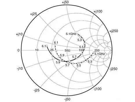
Extract the input and output impedance in the frequency range of 5.3GHz ~ 5.5ghz from the curve, as shown in the following table:
| Frequency Range | 5.3GHZ | 5.35GHZ | 5.4GHZ | 5.45GHZ | 5.5GHZ |
| Impedance Input | 84+j*52.8 | 94.2+j*47.3 | 103.4+j*38.3 | 109.4+j*25.8 | 111+j*11.9 |
| Impedance Output | 108.6+j*61.7 | 95.5+j*58.1 | 85.2+j*53.8 | 75.3+j*49.4 | 67.6+j*44.7 |
The impedance matching circuit is designed according to the obtained impedance information.
The circuit structure of input and output impedance matching is shown in the following figure:

The input and output impedance matching circuit parameters are optimized respectively. After the design is completed, the return loss is tested. The test results are as follows:
| Frequency Range | 5.2GHZ | 5.3GHZ | 5.4GHZ | 5.5GHZ | 5.6GHZ | 5.7GHZ |
| Return loss Input | -15.7 | -16.4 | -16.6 | -17.0 | -17.6 | -16.3 |
| Return loss Output | -15.1 | -20.7 | -16.0 | -15.1 | -16.5 | -16.4 |
In the small-signal environment, the power transmission performance of the matching circuit is good. Connect the matching circuit to the input and output end of the power amplifier tube and scan the power and gain under the excitation of high signal power:
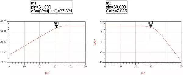
The scanning results show that the output power and gain of the power amplifier circuit are insufficient under power excitation.
We first optimize the input impedance matching circuit parameters to improve the gain and then optimize the output matching circuit parameters to meet the condition of maximum output power. Power and gain scanning again after circuit optimization:
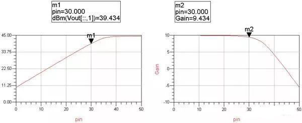
After optimization, the saturated power output of the power amplifier circuit is greater than 8W and the gain is greater than 9dB, which meets the index requirements. After the circuit design is completed, select the appropriate high-frequency board to realize the circuit engineering.
Reliability is an important factor in the design of a power amplifier circuit.
The reliability of the power amplifier circuit is mainly affected by several factors, such as the power capacity of the transmission line, power reflection of the matching circuit, heat dissipation environment of the power amplifier, and so on. Considering the high-power transmission of the matching circuit, when selecting a high-frequency plate, it is necessary to increase the thickness of copper foil of transmission line to improve the power capacity and heat dissipation conditions of transmission line. The yield of microstrip matching circuit is greatly affected by the consistency of high-frequency plate. In order to reduce the probability of power amplifier damage caused by power reflection caused by parameter drift of matching circuit, the parameters of high-frequency plate should be stable and have good batch consistency. If there is no heat dissipation, the power amplifier circuit will be damaged due to the gradual rise of temperature. In view of this, the selection of a power amplifier circuit board should be conducive to the heat dissipation design.
The RT / Duroid 5880 plate product model of Rogers has a long history, high maturity, and stability, and can be customized. When customizing the plate, the thickness of copper foil on the upper surface can be specified as 1oz to improve the power capacity of the actual circuit, while a 2mm thick copper metal layer is attached to the lower surface to provide a good heat dissipation environment for the power amplifier circuit and reduce the probability of power amplifier tube breakdown caused by temperature rise due to poor heat dissipation. In the process of engineering implementation, the author found that using RT / Duroid 5880 plate is very helpful to improve the reliability of the power amplifier circuit as a whole.
The customized high-frequency board is used for circuit engineering implementation, and the optimized impedance matching circuit of the power amplifier tube microstrip transmission line:
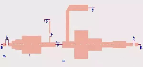
Extract the information on circuit structure size and plate parameters to manufacture microstrip circuit. Use 30dBm signal to excite the power amplifier and test the output power:
| Frequency Range | 5.3GHZ | 5.4GHZ | 5.5GHZ | 5.6GHZ | 5.7GHZ |
| Power Output | 39.5 | 39.4 | 39.4 | 39.2 | 39.1 |
| Gain(dB) | 9.5 | 9.4 | 9.4 | 9.2 | 9.1 |
The optimized power amplifier index meets the demand. Then use the network analyzer to test the microstrip input and output matching circuit:
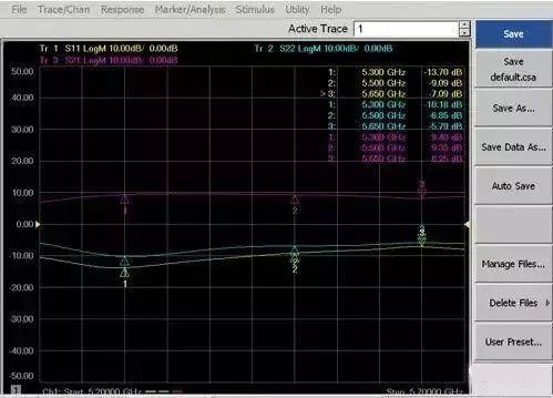
From the test results above, it is found that the return loss of the optimized matching circuit becomes worse. This is because the optimized matching circuit can better meet the index requirements of the power amplifier in the large signal working environment, but the index deviates in the small-signal test environment. In a word, after the realization of the final index, the matching circuit shows two different results by using two different test and analysis methods of small signal and large signal.
Summary
The design of an impedance matching circuit of a high-frequency power amplifier is one of the main engineering applications of microstrip transmission line. The power amplifier circuit has strong nonlinear characteristics, and its design and analysis method is complex. It is necessary to flexibly use microstrip transmission line to design and optimize the impedance matching circuit to meet the index requirements of the power amplifier. While meeting the index, reliability is also the focus of power amplifier circuit engineering.
