1. How many types of wireless base stations are there for 5G NR?
The capabilities of 5G NR wireless access must go far beyond previous generations of mobile communications. Examples of these capabilities include extremely high data rates, extremely low latency, extremely high reliability, energy efficiency, and extremely high device density, and will be enabled by the combination of LTE and the development of new radio access technologies.
The base station (BS) in the key technical components of 5G is divided into an active antenna system (AAS-Active Antenna System) base station and a standard wireless system (MSR-Multi-Standard Radio) base station. Below we introduce them one by one.
2. AAS-Active Antenna System
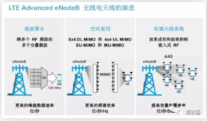
Active Antenna Systems (AAS) are advanced base station platforms that are optimized for cost, structure and performance. 4G Release 12 enhancements significantly impact how enhanced NodeB (eNodeB) radios are designed. Version 12 projects include new combinations of carrier aggregation, spatial multiplexing enhancements with downlink MIMO (multiple input/multiple output), and RF requirements required in AAS. The first diagram outlines some of the content of a Version 12 project with corresponding features and benefits.

In the 5G era, Massive MIMO is the backbone of its network, where 100 or more antenna elements will be used to achieve all kinds of better performance. But it is difficult to introduce the large element antennas (100 or more elements) required for Massive MIMO to traditional base stations, and it is impractical to connect more than 100 RF cables between each antenna element and the RF TRX element, while Also adds more RF losses. Therefore, using an AAS that combines the antenna and RF TRX unit (transmitter and receiver chain) into a single unit would be an effective solution to these problems.
The MSR BS specification is considered a non-AAS specification and defines conduction requirements because the antenna entity is not part of the MSR BS, just like LTE eNodeB, where the antenna is an external entity.
The evolution of AAS with integrated antennas initially led to the specification of AAS with a conducted interface and an OTA (over-the-air) interface, which was then enhanced to provide an OTA-only set of requirements, which led to 2 types of AAS and a corresponding set of requirements.
Hybrid AAS BS with Conducted and Radiated Interfaces
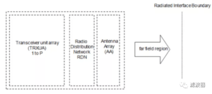
OTA AAS BS, it has only one radiation interface.
This results in the conducted and radiated compliance tests required for 5G BSs, which also depend on the frequency range the BS belongs to. In 5G NR, there are roughly two large frequency ranges specified in 3GPP. One is what we usually call (sub 6 GHz) and the other is what we usually call millimeter wave.

3. MSR-Multi-Standard Radio
The standard wireless system MSR base station specification is considered a non-AAS specification; it defines conduction requirements because the antenna entity is not part of the MSR base station, just like LTE eNodeBs, where the antenna is an external entity. As such, it has 4 different types of 5G NR base stations, each with different architectures and requirements.
BS 1-C type
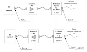
BS Type 1-C (Conducted) requirements apply to the BS Antenna Connector (Port A) for a single transmitter or receiver as well as a complete transceiver for configuration under normal operating conditions. If any external equipment is used, such as amplifiers, filters, or a combination of such equipment, the requirements apply to the far-end antenna connector (port B).

Type BS 1-H
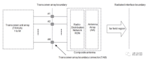
The BS Type 1-H (Hybrid) radio architecture is represented by three main functional blocks: Transceiver Element Array (TRXUA), Radio Distribution Network (RDN), and Antenna Array (AA). The point where the TXU or RXU connects to the RDN is called the “Transceiver Array Boundary Connector” (TAB connector).
The TAB connector is defined as the conductive reference point, the RDN distributes the TX output to the corresponding antenna path and antenna element, and distributes the RX input from the antenna path in the opposite direction, the RDN can be composed of passive power dividers and combiners, OTA requirements apply to the far-field at the radiating interface boundary.

BS 1-O and BS 2-O
BS Type 1-O and 2-O requirements apply to the far field covering the cell boundary. The OTA BS types here have no transceiver array boundaries or TAB connectors, they have no conduction requirements. Of these, Type 1-O requirements apply to base stations (BS) operating in FR1, while Type 2-O requirements apply to base stations (BS) operating in FR2.

