Preface
The third-order intercept point (IP3) is an important index to measure the linearity of a communication system, and it reflects the magnitude of the intermodulation distortion when the system is interfered with by a strong signal. When the IP3 of the system is high, it will be difficult to accurately test the IP3, because various factors in the test environment (such as the isolation, linearity and matching of the test accessories) can easily affect the high IP3 test.
In the microwave, multi-carrier communication system, one of the many test indicators is the third-order intermodulation intercept point IP3 (THIRD-ORDER INTERCEPT POINT), which is an important indicator to measure the linearity and distortion performance of the device.
In analog microwave communication, intermodulation distortion will produce adjacent channel signal crosstalk. Digital microwave communication, will reduce the spectrum utilization rate of the system and deteriorate the bit error rate.
The larger the capacity of the system, the higher the requirements for IP3; the higher the IP3, the better the linearity of the device, and the less distortion, therefore, it is also important to accurately measure the size of IP3.
Next, we will focus on the measurement methods of the third-order intermodulation intercept point.
Calculation of the third-order intermodulation intercept point
When two or more sinusoidal signals pass through the amplifier, due to the nonlinear effect of the amplifier, components including multiple frequencies will be output, among which the power level of the third-order intermodulation component is the largest, which is generated by the third-order term in the nonlinearity. , assuming that the frequencies of the two fundamental frequency signals are F1 and F2 respectively, then the frequencies of the third-order intermodulation components are 2F1-F2 and 2F2-F1. Since this frequency falls within the frequency band, it is the nonlinear product we are concerned about, such as Figure 1

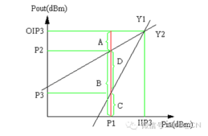
Figure 2 shows the curve of the fundamental frequency signal and the third-order intermodulation signal with the increase of input power:

It can be seen from the figure that when Pin gradually increases to IIP3, the fundamental frequency signal Y1 and the third-order intermodulation signal Y2 intersect, and the corresponding output power is OIP3. At this time, IIP3 is defined as: the output third-order intermodulation intercept point (INPUT THIRD -ORDERINTERCEPT POINT) OIP3 is defined as the OUTPUT THIRD-ORDERINTERCEPT POINT.
As shown in Figure B, the slope of the first-order intermodulation (ie fundamental frequency signal) Y1 of the amplifier is represented by G, then the slope of the third-order intermodulation signal Y2 is 3G/G, that is: the third-order intermodulation signal output The slope of the power is three times the slope of the fundamental output power.
When the input power Pin is equal to IIP3, the corresponding fundamental frequency output power and the third-order intermodulation signal output power are both equal to OIP3. The third-order intermodulation we want to measure is the difference between the corresponding input and output power levels in this case. size. In actual situations, the input power and output power are relatively large at this time, which is inconvenient to measure.
Therefore, the following measurement method can usually be taken: as shown in Figure B, an input power P1 is given to the amplifier, and the corresponding output power is B, then:
B+A=OIP3 (1)
And because the slope of the output power of the third-order intermodulation signal is three times the slope of the output power of the fundamental frequency, therefore:
A=D/2 (2)
It can be seen from the diagram that: D=P2-P3 (3)
Substituting 3 into 2, we get: A=(P2-P3)/2 (4)
Substituting 4 into 1, we get: OIP3=(P2-P3)/2+B (5)
After calculating OIP3, it is not difficult to know: IIP3=OIP3-GAIN (6)
Measuring Equipment of the third-order intermodulation intercept point

Example
Device Under Test: Low Noise Amplifier
Frequency range: 880~930MHz
Noise figure: 2.2dB. Return loss: >18 dB.
Gain: 20 dB. Power supply: +12V, 250mA.
Equipments:
Signal source: HP8648B
Spectrum analyzer: Agilent8560EC
Power supply: HP3631A.
Measurement steps:
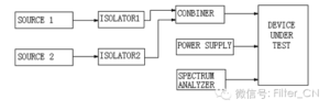
A. Connect the test bench as shown in Figure B.
B. Adjust the frequency of the two signal sources to two adjacent frequencies in the band, such as F1=901MHz; F2=902MHz
C. Set the attenuation level of the spectrum analyzer to 10 dB, the reference level to 0 dB, the range (SPAN): 5MHz, and the center frequency: 901.5MHz.
D. Adjust the regulated power supply to: DC12V.
E. Turn on the regulated power supply, turn on the signal source respectively, and fine-tune the signal source so that the output of the amplifier is -7dBm.
F. Turn on the two signal sources at the same time, and you can see the fundamental frequency signal and the third-order intermodulation signal on the spectrum analyzer at the same time.
G. Press the PEAK SEARCH key, the MARKER point will search to the peak point of the fundamental frequency signal. Then press MARKER DELTA, and then press the NEXT LIFT or NEXT RIGHT key (the specific key is determined according to the position of the MARKER point). At this time, the MARKER DELTA can be directly read from the spectrum analyzer (ie: the value of D shown in Figure 2 ).
H. Calculate the values of OIP3 and IIP3 by formula 5 and formula 6.
Assumption: The value of MARKER DELTA read from the spectrum analyzer is 70.
Then: the amplifier’s
OIP3=70/2+(-7)=28dBm. IIP3=28-20=8dBm.
