What is Antenna Pattern?
Antenna pattern is also called radiation pattern and far-field pattern. The antenna gain cannot be obtained from the pattern, but the direction coefficient is obtained from the pattern. Antenna gain = directional coefficient * antenna efficiency. Therefore, it is certain that the directional coefficient is greater than the gain.
The antenna gain is mainly shown by the test of pattern. There are many kinds of test systems for a testing pattern. That is, the darkroom. The test result in the darkroom is only a result compared with the ideal symmetrical oscillator. It is known that the gain of an ideal symmetrical oscillator is 2.15db. In this way, the gain of the antenna can be calculated according to the test level.
G=D*N%.
In general, the efficiency of the antenna is not 100%, so g < D. When calculating the direction coefficient D of the antenna, it is usually calculated according to the lobe width of the main lobe shown in the pattern, such as the half-power lobe width, that is, the lobe width when the level drops by 3dB.
Antenna gain
Antenna gain refers to the ratio of the power density of the signal generated by the actual antenna and the ideal radiation unit at the same point in space under the condition of equal input power. It quantitatively describes the degree of concentrated radiation of input power by an antenna. Obviously, the gain is closely related to the antenna pattern. The narrower the main lobe is, the smaller the side lobe is, and the higher the gain is.
Antenna gain is used to measure the ability of the antenna to transmit and receive signals in a specific direction. It is one of the most important parameters to select the base station antenna. Generally speaking, the increase of gain mainly depends on reducing the lobe width vertically facing the radiation, while maintaining the omnidirectional radiation performance on the horizontal plane.
Antenna gain is very important for the operation quality of mobile communication systems because it determines the signal level at the edge of the cell. Increasing the gain can increase the coverage of the network in a certain direction, or increase the gain margin within a certain range. Any cellular system is a two-way process. Increasing the gain of the antenna can reduce the gain Budget Margin of the two-way system at the same time. In addition, the parameters representing the antenna gain are DBD and DBI. DBI is the gain relative to the point source antenna, and the radiation in all directions is uniform; The gain of DBD relative to the symmetrical array antenna DBI = DBD + 2.15. Under the same conditions, the higher the gain, the farther the radio wave propagation distance. Generally, the antenna gain of GSM directional base station is 18dbi and that of an omnidirectional base station is 11dbi.
Characteristic parameters of antenna pattern:
In order to compare the pattern characteristics of various antennas, some characteristic parameters need to be specified. It mainly includes main lobe width, sidelobe level, front to back ratio, directional coefficient, etc.
1. Main lobe width: it is a physical quantity to measure the sharpness of the maximum radiation area of the antenna. Generally, the width between two half-power points of the main lobe of the antenna pattern is taken.
2. Sidelobe level: refers to the level of the first sidelobe closest to the main lobe and with the highest level, generally expressed in decibels.
3. Front to back ratio: refers to the ratio of the maximum radiation direction (forward) level to its opposite direction (backward) level, usually in decibels.
4. Direction coefficient: the ratio of the radiation power flow density of the antenna in the maximum radiation direction at a certain distance from the antenna to the radiation power flow density of the ideal non-directional antenna with the same radiation power at the same distance.
Antenna pattern drawing
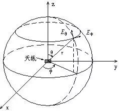
The antenna pattern is a graph that represents the relationship between antenna radiation characteristics (field strength, amplitude, phase, polarization) and spatial angle. The complete pattern is a three-dimensional spatial graph, as shown in Figure 3.1. It is drawn by taking the phase center of the antenna as the spherical center (coordinate origin) and measuring its radiation characteristics point by point on a spherical surface with a large radius R. Measure the amplitude of the field strength to obtain the field strength pattern; The power pattern is obtained by measuring the power; The polarization pattern is obtained by measuring the polarization; The phase pattern is obtained by measuring the phase. Unless otherwise specified, all the patterns mentioned in this book refer to the field intensity amplitude pattern. The mapping of three-dimensional spatial pattern is very troublesome. In practical work, it is generally only necessary to measure the pattern of horizontal and vertical planes (i.e. XY plane and XZ plane).
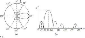
The antenna pattern can be drawn in polar coordinates or rectangular coordinates. The polar coordinate pattern is intuitive and simple. From the pattern, we can directly see the spatial distribution characteristics of antenna radiation field strength. However, when the main lobe of the antenna pattern is narrow and the side lobe level is low, the rectangular coordinate drawing method shows greater advantages. Because the abscissa representing the angle and the ordinate representing the radiation intensity can be selected arbitrarily. For example, the main lobe width of less than 1 ° can be clearly expressed, while the polar coordinates cannot be drawn. Fig. 2 shows two coordinate representations of the same antenna pattern.
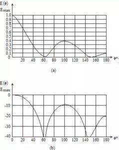
Generally, when drawing the pattern, it is normalized, that is, the radial length (polar coordinate) or ordinate value (rectangular coordinate) is based on the relative field strength E( θ,φ)/ Emax, here’s E( θ,φ) Is the field strength value in any direction, and Emax is the field strength value in the maximum radiation direction. Therefore, the normalized maximum is 1. The pattern of very low sidelobe level antenna is mostly expressed in dB, and the normalized maximum value is zero dB. Fig. 3 shows the same antenna pattern expressed by normalized field strength and decibel value in rectangular coordinates.